Negative Feedback in Circuit with Operational Amplifier MAA741
Introduction
The goal of this task is to get familiar with the properties of negative feedback and with the functional block of operational amplifier type.
Instructions
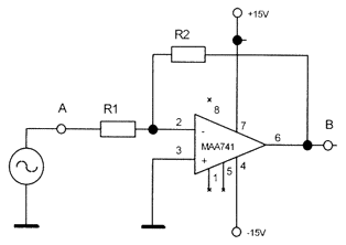
- Propose negative feedback and connection of operational amplifier for cases of overall amplification K = 10 and K = -10 (non-inverting and inverting scheme).

Figure 1: Circuit scheme with negative feedback During the preparation, propose (in your laboratory diary) complete scheme of this two cases, that you will connect in the practicum (including the necessary calculations and derivations, that you will mention even later in the protocol). The necessary theory was explained at the lectures. - Connect the supply voltage to the operational amplifier according to the manufacturer's recommendation and get familiar with the scheme of the socket of the integrated circuit according to the catalogue. Notice the convention of drawing the suply circuits in the scheme, and the real connection of the power supplies to the circuit of the amplifier.
- Measure the amplification of the amplifier and its dynamical range for DC signal and for the both cases from item 1.
- Compare the measured results to the theoretically derived values and explain the possible difference.
Notes:
- dynamical range means the range of possible output voltages
- measure for input DC voltages between -1.5 and +1.5 Volts,
- prove the functionality also for AC signals 100-1000 Hz
Josef Blažej - contact - blazej troja.fjfi.cvut.cz - phone: +420 224 358 659
Czech Technical University in Prague - Faculty of Nuclear Sciences and Physical Engineering
Brehova 7, 115 19 Prague 1, Czech Republic
Czech Technical University in Prague - Faculty of Nuclear Sciences and Physical Engineering
Brehova 7, 115 19 Prague 1, Czech Republic