Transistor Amplifier
Instructions:
- Propose values of the devices at Fig. 1 so that the operation point of the transistor Q1 will be in active mode - the voltage between collector and emittor must be 5 V.
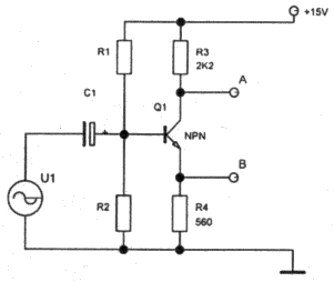
Figure 1: Scheme of the transistor amplifier Implement this circuit and prove the correctness of your proposal by measurement. Propose minimal value of the coupling capacitor on the input for frequency of 1 kHz. - Using the curve tracer, measure current amplification of the used transistor at operation point that you have used (from Fig. 1). Determine voltage amplification of the circuit at Fig. 1 for the outputs A and B. Compare your calculations to the measurement. Find out the dynamical range of the amplifier.
- Block the resistor R4 at Fig. 1 by capacitor of 100 microfarads (or more) and measure the amplification of the circuit for the outputs A and B again. (to block means to short-circuit the resistor for alternating current by parallel connection of the capacitor)
Notes:
- the convention for amplification of a circuit is, that amplification of an inverting circuit has minus sign.
- dynamic range means the range of the output voltage, within which there is no significant distortion of the amplified signal.
Josef Blažej - contact - blazej troja.fjfi.cvut.cz - phone: +420 224 358 659
Czech Technical University in Prague - Faculty of Nuclear Sciences and Physical Engineering
Brehova 7, 115 19 Prague 1, Czech Republic
Czech Technical University in Prague - Faculty of Nuclear Sciences and Physical Engineering
Brehova 7, 115 19 Prague 1, Czech Republic