Optical components spectral characteristics
warning
This is partially old version from acad. year 05/06. The new spectrophotometer Shimadzu UV-3600 is installed. The Introduction may be obsolete. All other parts (Goals, Instruction, Requested results) are up to date and valid.
Introduction
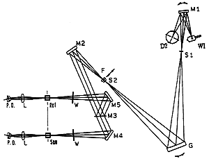
The optical scheme of spectrophotometer Shimadzu UV1601 is on fig. 7.1. See the technical documentation for details.
 Fig. 7.1: Spectrophotometer optical scheme.
D2-Deuterium lamp
WI-Halogen lamp
F-Filter
G-Diffraction grating
S1-Entrance slit
S2-Exit slit
W-Window Plate
M1-M5-Mirrors (M3 is a half-mirror)
L-Lens
Sam-Sample cell
Ref-Reference cell
P.D.-Photodiodes
Keep in the mind two independent light sources in this device. They are mechanically switched on selectable wavelength in region 295 - 364 nm. Avoid any mismatching interpretation of leakage peaks.
Goal
Practical use of spectrophotometer. The measurement with optical samples and exercise with optical properties of mirrors and crystals. The determination of physical character of optical element based on its spectral characteristics.
Instructions
- Start control computer.
- Start the spectrophotometer using big green button labeled POWER.
- On computer run application UVProbe (shortcut is on the desktop)
- In application press button Connect. Wait for initialisation procedure (about 15 min.). All items should be done with status "passed". Otherwise call immediatly anybody from staff.
- Make sure that the spectrophotometer is empty (no inserted samples) and by software button "Baseline" calibrate the baseline. Due to thermal drifts this operation should be repeated after each restart or after several hours of operation. The baseline have to be recalibrated also when some supports of samples is limiting the measuring optical beams (see printed manual on site).
- In menu Edit-Method find the table Measurement and set the wavelength range to 185-1600 nm. Make sure that in table Instrument Parameters the Measuring mode is set to Transmittance. Do not change any other parameters!
- Avoid any touching with sample optical surfaces. If one of surfaces on sample is preferred (sign on side) then it should be the input face for probing beam.
Requested results
- Graphs of all spectral characteristics.
- The right assignment to listed well-known materials
- dielectric narrowband filter for ruby laser
- RG7 filter (highpass over 700 nm)
- protective glasses for Nd:YAG laser
- ruby laser crystal
- mirror for Nd:YAG laser
- mirror for ruby laser
- infrared filter (highpass 600 nm)
- silicon wafer
- dark spectacle glass
- For each identified sample complete following details:
- dielectric narrowband filter for ruby laser
- the width transmission band Δλ for ruby laser
the maximum transmission wavelength λmax - RG7 filter
- wavelength λ1/2 when T = 0.5
physical width of filter
compute internal transmission τi for 1064 nm wavelength - ruby crystal
- find all maximum absorption peaks λmax and its width δλ
for each peaks compute absorption coefficients α (from internal absorption)
Decide if the system energetically is 3- or 4-level
Find the reason of local absorption maximum at 694 nm - mirror for Nd:YAG laser
- estimate wavelengths interval where can be used as a high reflectivity mirror
(high reflectivity (HR) mirror is a mirror with reflectivity over 98 %)
Decide and give reasons for using this mirror as a HR mirror for diode pumping on 808 nm - mirror for ruby laser
- Estimate wavelengths interval where can be used as a HR mirror
- laser crystal Nd:YVO4
- Find the position of significant maxima in range 800-900 nm. Which of them are useful for diode pumping of Nd:YVO4?
Estimate the optimal pumping laser diode line half-width
Indicate a list of wavelengths generated by Nd:YVO4. Is it possible to observe the transmittance dip on these wavelenght? Why?
Decide if the system energetically is 3- or 4-level - laser crystal Er:glass
- Find the position of significant maxima in range 800-1000 nm. Which of them are useful for diode pumping of Er:glass?
Estimate the optimal pumping laser diode line half-width
Indicate a list of wavelengths generated by Er:glass. Is it possible to observe the transmittance dip on these wavelenght? Why?
Decide if the system energetically is 3- or 4-level - crystal Cr:YAG
- Decide the application of this crystal in laser technique
Measure the width of sample and calculate internal absorption coefficient at 1064 nm wavelength. The Fresnel losses on faces should be substracted.
- The physical reason for results interpretation when the sample cross section is smaller then size of probing beam.
References
- Shimadzu pages
- https://www.shimadzu.com/an/molecular_spectro/uv/uv-3600plus.html
- Nikogosyan, D.N., Properties of Optical and Laser-Related Materials: A Handbook
- material properties
Czech Technical University in Prague - Faculty of Nuclear Sciences and Physical Engineering
Brehova 7, 115 19 Prague 1, Czech Republic