v. 2012/2013
Diode pumped Nd:YAG laser
Introduction
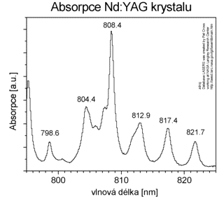
 Fig. 3.1: The typical Nd:YAG absorption spectrum.
Goal
To find a dependence of transmittance of Nd:YAG crystal on wavelength in laser diode emission spectral region. The identification of laser diode emission line with minimum transmittance on base of knowledge typical Nd:YAG crystal absorption spectrum. The determination of electron lifetime on energetic level 4F3/2.
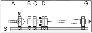
 Fig. 3.2: The kit configuration for absorption measurement.
Instructions
- Place elements of experimental setup according fig. 3.2 (A, B, C). The role of lens is to focus a maximum energy into focus inside crystal.
- Link optical axis using visualizers plate when pumping diode is switched on without modulation and insert crystal (D) in focus.
- Set minimum temperature on laser diode.
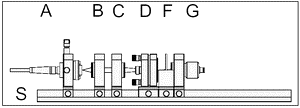
 Fig. 3.3: The kit configuration for lifetime measurement.
 - Set maximum current through diode. Place detector sufficiently far from crystal to prevent the saturation or insert additional diffusion elements. The recommended maximum amplitude (over entire temperature range) on scope is 1 V.
- Increase slowly temperature and see on scope and record the changes of dc level proportional to intensity of passing radiation through crystal.
- Find absolute absorption maximum and set temperature to it. Step by step decrease current through diode and compensate it by temperature change back to local signal minimum. Record every triplets (current, temperature and signal). This optimalization allows a constant wavelength radiation control.
- Set the current back to maximum and temperature to absorption maximum, insert filter RG1000 in front of detector and shift the detector close to crystal. To have maximum contrast remove RG1000 from its holder and place detector really close to crystal. Switch control unit to internal modulation mode and set frequency so low so emission can decrease to zero level.
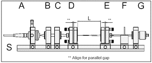
 Fig. 3.4: The kit configuration for laser. A the pumping diode, B,C lenses, D crystal, E output mirror, F filter, G detector, L length of resonator, S optical bench
 - Read on the oscilloscope the lifetime of spontaneous emission the time when intensity fall to 1/e (~37 %) of initial amplitude. Then switch the modulation back to cw mode.
- Compute the resonator stability interval using geometrical parameters from user manual. Disregard crystal optical bulkiness. And place output mirror roughly in half of stability interval.
- Set resonator to have planes signed ** on fig. 3.4 to be parallel.
- Monitor output energy on detector with filter and tune resonator for maximum output energy. The resonator is most sensitive for mirror tilt when pumping energy is low, just above threshold.
- Change step by step current and temperature to ensure a constant output wavelength and measure output energy from laser.
- Switch pumping to modulated mode and just above laser threshold. Observe and record the spiking the temporal profile of laser radiating in relation with pumping modulation phase.
Requested results
- The graph of absorption of Nd:YAG crystal as a function of temperature of pumping diode for a constant current. Pay attention to right axis labels. Assign (in graph) the absolute wavelengths for individual peaks (see fig. 3.1 for help).
- The value of electron lifetime on neodymium 4F3/2 energetic level.
- The graph of temperature of pumping diode as a function of current for constant wavelength operation.
- The graph of pumping diode output power as a function of current on constant wavelength.
- The graph of laser output energy as a function of pumping energy (not temperature or current). Tag (in graph) the laser threshold.
- The commented plot of spiking.
References
- Yariv, A., Quantum Electronics
- Nd:YAG laser theory
- MEOS laser kit
- https://www.tau.ac.il/~lab3/72_Laser_res/yag_manual.pdf
Josef Blaej contact blazej troja.fjfi.cvut.cz phone: +420 224 358 659
Czech Technical University in Prague Faculty of Nuclear Sciences and Physical Engineering
Brehova 7, 115 19 Prague 1, Czech Republic
Czech Technical University in Prague Faculty of Nuclear Sciences and Physical Engineering
Brehova 7, 115 19 Prague 1, Czech Republic