v. 2013/2014
Free-running and Q-switched Nd:YAG laser, laser amplifier and second harmonic generation
Goals
- Set-up and run Nd:YAG laser in free-running mode. Measure energetic, temporal, and spatial laser beam chracteristics.
- Set-up and run Nd:YAG laser in Q-switch mode. Compare single- and multi-mode regimes. Measure and compare energetic and temporal laser beam chracteristics.
- Measure amplification of optical pulses generated in Q-switched mode.
- KDP crystal synchronism setup and measure of second harmonic generation efficiency in Q-switch mode.
Instructions
A. Laser characteristics in multi-mode free-running mode
- Set up the center of laser crystal into the He-Ne laser beam.
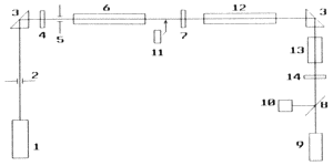
 Fig. 1.1: The laser kit configuration block scheme for experiments
Components on the scheme on fig. 1.1 are marked: 1 – He-Ne laser, 2 – aperture, 3 – prism, 4 – resonator back mirror (100% reflectivity), 5 – aperture, 6 – laser crystal, 7 – resonator output mirror, 8, 9, 10 – beam splitter, energy meter, photodiode (these accessories are not on the draw), 11 – LIF crystal for passive Q-switching, 12 – amplifier laser crystal, 13 – KDP crystal, 14 – filter absorbing 1.06 μm. (experiments start without crystal 11) - Set up the laser resonator by beam coupling.
- Run the laser (according to additional oral tutor instructions) and tune it on maximum output energy and as circular profile as possible by finely tilting resonator mirrors.
- Record the output beam profile on the photo paper (use black paper for free-running mode and gray paper for Q-switched mode) and measure its area S.
- Read the oscillator source voltage (the conversion table is on the source side) and compute the energy stored in the capacitors (C = 100 μF) representing pumping energy Eb.
- Find the threshold pumping energy Eth for free-running mode.
- Measure the output energy Eout as a function of pumping energy.
- Observe the generated radiation temporal profile on oscilloscope and estimate generation time τFR for various pumping energies:
- just above Eth
- for middle of interval used Eb
- for maximal Eb
- Insert the LIF crystal inside the resonator (using altitudinal feed) to have the He-Ne laser beam in the center and along the crystal axis.
- Setup laser amplifier active element to optical axis of justified oscillator. Setup laser generation in transversally multimode regime (without tranversal limitation of resonator)
- Measure input and output amplifier energy for variable oscillator pumping and compute amplification coefficient G.
- Repeat instructions 4-9 for Q-switched mode.
- Switch to Q-switched mode.
- Adjust synchronism angle to optimum by maximum SHG energy in KDP crystal.
- Adjust angle back and measure conversion efficiency as a function of input energy.
B. Laser characteristics in Q-switched mode
Requested results
- Two tables for both modes, independent variable Eb, dependent output energy E, efficiency η=E/Eb, surface density of energy W=E/S, power Pavg=E/τ.
- Graphs E(Eb); W(Eb); τ(Eb); Pstr(Eb), in each graph two curves (free-running and Q-switched).
- Two G(Ein) curves in one graph for both laser operation modes.
- The graph of second harmonic output energy and conversion efficiency as a function of input energy.
References
- Yariv, A., Quantum Electronics, chapters 7.3 – 7.4
- rare-earth lasers
- MEOS - Q-switch theory (pages 9,10)
- https://www.tau.ac.il/~lab3/72_Laser_res/yag_manual.pdf
Annex
Move cursor over graph to read data. Data by Petr Navrátil, 2014.
Josef Blažej - contact - blazej fjfi.cvut.cz - phone: +420 224 358 659
Czech Technical University in Prague - Faculty of Nuclear Sciences and Physical Engineering
Brehova 7, 115 19 Prague 1, Czech Republic
Czech Technical University in Prague - Faculty of Nuclear Sciences and Physical Engineering
Brehova 7, 115 19 Prague 1, Czech Republic